

Next: Related Work Up: No Title Previous: Theoretical Foundation


Next: Related Work
Up: No Title
Previous: Theoretical
Foundation
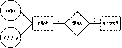
The informal definition of Entity-Relationship (ER) diagrams is directly taken from [19] in order to demonstrate the expressiveness of our specification language and the reasoning capabilities of our DL system. Figure 2 shows an example ER diagram specifying a relationship between a pilot and an aircraft. We assume a few primitive concepts (denoted in slanted font) and spatial relations (touching, containing, linked_with, text_value) representing geometrical objects (rectangle, circle, diamond, line, text) and their relationships.

Figure 2: A simple entity-relationship diagram
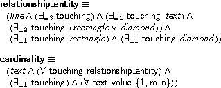
 A relationship-entity
connection is a line that touches exactly one text label (expressing
cardinality) and two other regions (rectangle or diamond). A cardinality
is a text string with values chosen from the set
 .
.

 An attribute-entity
connection is a line that touches only two regions (circle or rectangle)
and no text string.

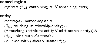
 An entity
is a rectangle that contains its name. It touches at least one
relationship-entity and optionally some attribute-entity connectors.
It is linked with at least one diamond.

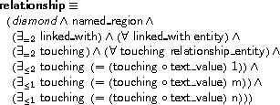
 A relationship
is a diamond that contains its name. It touches one relationship-entity
and optionally some attribute-entity connectors. It is linked with two
entities.

 An attribute is
a circle that contains its name. It touches one attribute-entity connector
and is linked with an entity.
