Lab #1
This lab
covers the basics of Arduino programming including:
·
technical
specifications and capabilities of an Arduino board
·
use
of the Arduino programming IDE and an external text editor
·
how
to turn on the built-in LED at specific intervals
·
printing
text to the screen of the PC
·
reading
the Arduino clock
·
how
to save printed output to a text file and plot it with Microsoft Excel
The Arduino
labs cover some of the most useful Arduino library functions. If you require more information about the
function library it can be obtained here
https://www.arduino.cc/en/Reference/HomePage
Note that the
purpose
of the labs is to provide an introduction to Arduino programming. There are some other topics including basics
of mechatronics, microcontrollers, and wiring in the labs. However, the purpose of these topics is to
support the Arduino programming topic and provide reference information that
will prove useful in other courses. You
just need to carefully follow the instructions for these topics. Therefore, you are only responsible for the
topic of Arduino programming in MECH 215 (i.e. lab reports,
assignments, and the final exam).
Arduino
programming involves using basic Arduino library functions to perform various
tasks. Students are not expected to
remember the names of each function (they would be provided on the exam), but
they are expected to understand how to use them and apply them to simple
mechatronics / robotics problems. Since
the Arduino is very user friendly this task is not so difficult even though the
topics of microcontrollers and mechatronics can become challenging at advanced
instruction levels. The focus of the
labs is on an introduction to Arduino programming to provide some basic C++
programming experience for mechatronic applications.
Arduino
Technical Specifications
The following
table provides the basic technical specifications for the Iteaduino Nano
(Arduino compatible) microcontroller used in our lab.
|
Microcontroller
model |
Atmel
ATmega328 |
|
Microcontroller
type |
8-bit AVR
RISC |
|
Microcontroller
clock frequency |
16
MHz |
|
Flash
memory (to store programs) |
32
KB |
|
SRAM
(memory to store variables) |
2
KB |
|
EEPROM
(memory for permanent variable storage) |
1
KB |
|
Microcontroller
operating voltage |
5V |
|
Power
supply voltage |
7
to 12 V |
|
Power
consumption (in addition to any power loads) |
45
mA (with 7V power supply) |
|
Number
of Digital Input / Output (DIO) pins (0V low, 5V high) |
14 |
|
Number
of DIO pins with PWM (analog output) capability |
6 |
|
10-bit
Analog to Digital Conversion (ADC) input pins* |
8 |
|
5V
/ VCC pin maximum DC current |
200
mA |
|
GND
pins maximum DC current |
200
mA per pin (400 mA total) |
|
3.3V
pin maximum DC current |
50
mA |
|
Maximum
DC current for each DIO pin |
40
mA (20 mA recommended) |
|
Maximum
total DC current for all pins |
400
mA |
*Note that
the ADC pins can be configured and used for DIO if required.
The Iteaduino
Nano was chosen over other boards such as the Arduino Uno and Mega since it’s
inexpensive and very small / light. The
size makes it more useful for small and flying robots (such as those in MECH
390). Here is a picture of the Iteaduino
Nano with the pins labelled. Please make
careful note of this diagram since connecting the wrong component or
wire to the wrong pin can easily damage your board.
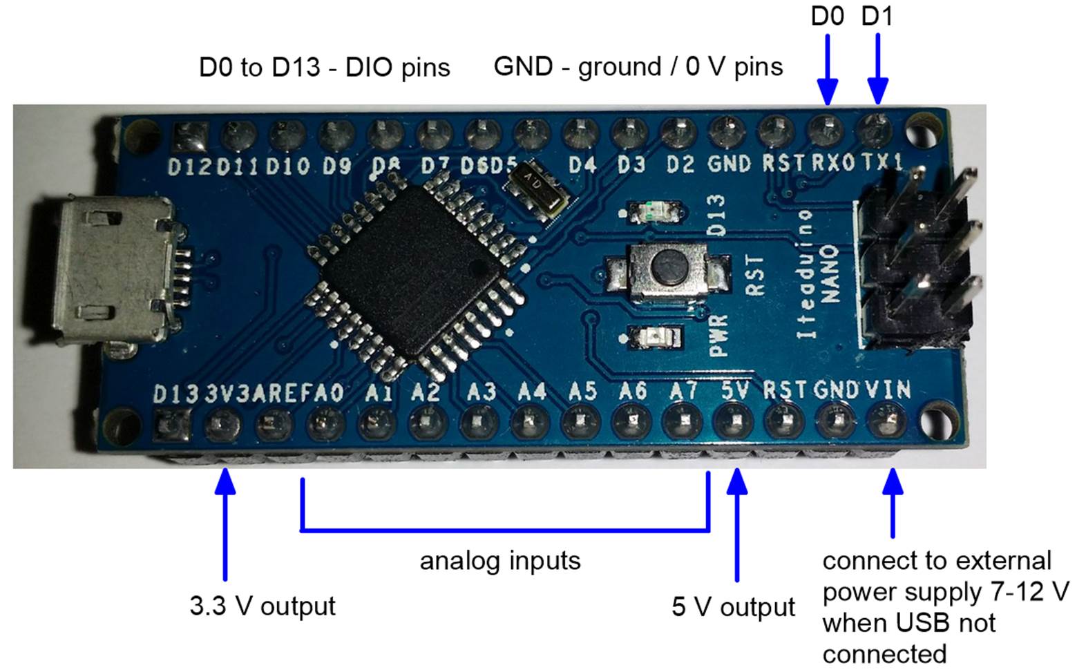
Lab Tip: The Digital Input
/ Output (DIO) pins on an Arduino (D0 to D13) are often just referred to
as pin 1 to pin 13 (the D letter is not used).
For example, pin 7 refers to pin D7.
The analog inputs are referred to as A0 to A7. Don’t confuse pin 7 with pin A7.
Don’t try
connecting / wiring the components together at this point since you can
accidentally damage them if not done correctly.
Wiring will be covered in detail in Lab #2. More detailed technical specifications and
information can be obtained here:
https://www.itead.cc/wiki/Iteaduino_Nano
The Arduino
Uno is a very similar board to the Iteaduino Nano (main difference is 6 ADC pins
instead of 8 ADC pins). The
documentation for the UNO is therefore applicable to the Iteaduino Nano.
https://www.arduino.cc/en/Main/ArduinoBoardUno
The
specifications in the table will now be discussed. The microcontroller used in this board is the
Atmel ATmega328. This is the most
popular microcontroller used in Arduino and compatible boards. It is an 8-bit microcontroller which
basically means the processor manipulates 8-bit data types (representing 0-255)
most efficiently. Larger data types such
as 16-bit and 32-bit take longer to process, so the processor is not as fast
for variable types such as floats and doubles.
Note that a typical PC has 32-bit or 64-bit microprocessors so it is
much faster processing floats and doubles.
The clock cycle of the ATmega328 is 16 MHz. This is related to the number of operations
the processor can perform per second. A
typical PC has a clock speed of 2,000 MHz so it’s much faster in this respect
too. While the ATmega328 (a typical
8-bit microcontroller) has much less capability than a PC, it is much less
expensive ($1.5 in bulk) and uses much less power (0.3 W vs. 15+ W). Therefore, it’s better suited for
mechatronics applications that are power and cost sensitive. Microcontrollers also have less memory than a
PC. In the table above it can be seen
that it has 32 KB to store programs and 2 KB to store variables. The EEPROM is like a mini hard drive to store
parameters (1KB worth) when the microcontroller power is turned off. The memory and speed limitations of an
Arduino must be carefully considered when programming. The amount of memory used by the program and
variables is indicated in the output window of the Arduino IDE after a program
has compiled. Make sure this is within
the limits when making your program.
It’s worth noting that a micro SD drive can be added to an Arduino board
in order to provide some hard drive like storage for data logging, e.g.
http://www.robotshop.com/ca/en/microsd-adapter-arduino.html
Information
can also be sent from the Arduino to the PC using the USB cable (if it’s
connected).
The Arduino
program is permanently stored in flash memory (like a USB flash drive) and
automatically executed when the Arduino is connected to a power supply (USB or
battery), a program is uploaded from the IDE, or reset (by pressing the RST
button or connecting a RST pin to GND).
Therefore, the PC USB connection is only required when programming the
Arduino. Once the Arduino has been
programmed it can be used without the PC.
The Arduino power comes from the USB cable when connected to the PC and
from the Vin pin (7-12V) when not connected to the USB.
Lab Tip: When connecting the Arduino to the USB cable
be gentle since the micro USB connector
is not that strong. It can be pulled off
the board with repeated rough handling.
It’s normally best to disconnect the Arduino using the regular USB
connector that goes into the PC.
The Iteaduino
Nano has 14 Digital Input / Output (DIO) pins as described in the
specifications table above. When a pin
is 0V (with respect to the ground/GND pin), the pin state is called low. When a pin is 5V (with respect to GND) the
pin state is called high. Each pin can be
configured as an input or output using an Arduino library function. More detailed information about inputs and
outputs is described in the background section below.
It’s very
important to note that the Arduino has strict limitations on the amount
of current allowed for its pins.
If an output or power / GND pin requires too much current the board will
be damaged (burned out pin, etc.). Note
that input pins (ADC and DIO pins configured as inputs) will have acceptable
currents as long as the pin voltage is between 0 to 5V. Since the current
capability of the Arduino is relatively small, the board should only be used to
supply power to sensors with the 5V, 3.3V, and GND pins (provided they are low
current) and not for actuators such as motors.
Actuators such as motors should be powered by separate amplifiers and
power supplies (i.e. like your stereo speakers). The following link provides a good list of
pin connections and scenarios that may damage an Arduino. Please study it carefully.
http://www.rugged-circuits.com/10-ways-to-destroy-an-arduino/
Background
and Definitions
This section contains
some background material and definitions to help you understand the lab or in
case you haven’t fully covered some of the related topics in the lectures yet.
Arduino
programming involves the use of Arduino library functions. In C++ there are many library functions such
as cout, cin, sin(x), etc. which you have probably used already. A C++ function basically performs some
programming task. Some functions such as
sin(x) return a value you can use in your expressions. A function can also receive a parameter /
argument such as x in sin(x) or “hello” in cout << “hello”. This argument is used by the function in
performing the task. Arduino library
functions are similar although they can perform a wider variety of tasks such
as changing a pin to 5V. For example,
the following Arduino function reads its built-in clock and returns the time in
microseconds.
float t;
t = micros();
// t = 0.0 occurs when the Arduino board is first turned on
Arduino
programs have two special functions much like the main() function in a C++
program. Note there is no main()
function in an Arduino program. The
first function setup() gets executed only once when the program begins. It’s used to configure the Arduino (setting
pin input/output configurations, etc.) and initialize variables. The second function loop() gets called
repeatedly once setup() has executed like the code in a for loop. Note the repeated execution of loop() only
ends when you stop the program or turn off the board. In most cases, however, the user wants to
execute loop() forever.
The Arduino
uses global
variables in order to share variables between setup() and loop(). A global variable is indicated by being
declared outside a function. These variables
can be accessed by any function in the program.
For example,
int P; //
global variable
void
setup() {
int i = 1; // local variable
P = 7;
pinMode(P, OUTPUT); // configure pin
7 for output
}
void
loop() {
digitalWrite(P, HIGH); // set pin 7
to 5V
}
In this case,
both setup() and loop() use the global variable P to indicate which pin (pin 7)
is to be used in the program. Note that
both loop() and setup() can modify P. A local
variable is declared inside a function (see i in the above example). It can’t be used / accessed by another
function. It should be noted that most
variables in a C++ program are local variables such as those in a C++ main()
function. Too many global variables can
result in confusion and errors so they should be used sparingly. More information for micros(), setup(),
loop() and other functions will be discussed in the programming part of the
labs.
Microcontroller
boards such as the Arduino have digital input / output pins (DIO). These pins, typically referred to as pin 1,
pin 2, etc., can be configure as inputs or outputs using an Arduino library
function. The configuration can change
at any time but is normally set once in the setup() function. After the DIO pin has been configured it will
behave as either an input pin or output pin.
Digital input pins are typically used to measure the voltage of on/off
sensors such as mechanical switches.
Output pins are typically used to turn actuators such as motors or LEDs
on/off. Note that actuators normally
require an amplifier due to their high current requirement and cannot be driven
by output pins directly.
Lab Tip: Small
LEDs can be connected to output pins provided the current is small enough (less
than 40mA but 20mA ideal). However, most
LEDs require a resistor to be placed in series with the LED to keep the current
at an acceptable level. This will be
discussed more in the Lab #2 wiring directions.
Don’t connect any LEDs yet.
A digital
output pin produces a voltage on a given pin which can be set with an
Arduino library function. Note you could
measure this voltage with a multimeter or oscilloscope connecting the
black/ground line to the GND pin and the red/V line to the DIO pin. For the Arduino board an output pin is either
0V (with respect to the ground/GND) or 5V (with respect to the
ground/GND). When a pin is 0V, the pin
state is called low. When a pin is 5V
the pin state is called high. To
represent this on/off (i.e. binary) state Arduino uses the constants LOW
and HIGH. These constants can be considered integers
that have values of 0 for LOW and 1 for HIGH.
An output pin is 0V when it is set to LOW and 5V when set to HIGH. Outputs that take on binary values in this
manner are known as digital outputs. For
example, the following line sets pin 7 to 5V.
digitalWrite(7,
HIGH);
A digital
input pin measures the voltage applied to a given pin between 0 and
5V. If it’s outside of this range the
pin/board could be damaged. A digital
input also has an on/off (binary) state represented with the constants LOW and
HIGH. In this case, HIGH means the pin
has a voltage greater than 3V (normally just 5V) and LOW means the pin has a
voltage of less than 3V (normally just 0V).
Therefore, a voltage between 3V and 5V is considered HIGH and a voltage
between 0V and 3V is considered LOW. For
example, the following lines will set k equal to HIGH if the voltage on pin 7
is greater than 3V and set k equal to LOW if the voltage is less than 3V. Printing k to the screen would give 1 for
HIGH and 0 for LOW.
int k;
k =
digitalRead(7);
Note if a pin
voltage is 3V or close the input will not be that predictable due to
noise.
More
information about the “mysteries” of LOW and HIGH are given here.
https://www.arduino.cc/en/Reference/Constants
It should be
noted that the time it takes to read or write a DIO pin with Arduino functions
is very small (<1us for input and < 5us for output). Therefore, DIO pins can be used for
electronic communication and other tasks that require rapid response.
Note there
are some special Arduino boards that operate with 3.3V power so they define
high as 3.3V instead of 5V. In that
case, input voltages should be between 0 and 3.3V or you risk damaging the
board. The output voltage will range
between 0 and 3.3V. The threshold
voltage for LOW/HIGH is 2V instead of 3V.
Arduino
Programming
Lab Tip: You should only have one Arduino program file
(*.ino) in a folder and the folder should have the
same name as the program file.
Lab Tip: If you find the text on the Arduino board a
bit small to read you can use a magnifying glass App on your cell phone such as
“Army Knife”. It’s better to be safe
than sorry.
This video
covers the main programming part of the lab
http://users.encs.concordia.ca/~bwgordon/arduino_lab1.mp4
This video
provides some additional example / exercise problems
http://users.encs.concordia.ca/~bwgordon/arduino_lab1_examples.mp4
A rar file
that contains the source code files for this lesson is provided here
http://users.encs.concordia.ca/~bwgordon/arduino_lab1.rar
Lab
assignment
Lab Tip: Always disconnect the Arduino from the USB
port (its power supply) when making new wiring connections. This helps avoid accidentally damaging the
Arduino.
Lab Tip: When an Arduino is powered make sure not to
short circuit the pins by accident.
Shorting occurs when two or more pins are connected with a conductor
(wire, piece of metal, etc.). A typical
case is when two exposed wires / pins connected to Arduino pins get
crossed. This will likely damage the
Arduino board. A small piece of foam,
plastic, wood, or some type of mount (breadboard, etc.) can be used to hold the
Arduino to prevent shorting. When an
Arduino is performing some task do not touch the pins with your fingers or
erroneous inputs may occur. Finally, you
should avoid giving your Arduino static electricity shocks in the winter.
1) The
objective of this question is to determine how long it takes to execute an
Arduino library function, in this case the sin function. All functions require a certain amount of
time to execute. Due to the
computational limitations of an Arduino board it’s often important to determine
how long various parts of the program take to execute. The clock function micros() can be used to
measure the execution time of a function.
This is accomplished by measuring the time t1 before the function is
called and measuring the time t2 after the function is called. The difference dt = t2 – t1 is the time
required for the function to execute (assuming the time to execute micros() is
negligible). This value dt might vary
depending on the argument of the function and other tasks the Arduino is
doing. Therefore, it’s best to
repeatedly calculated dt in a for loop with a large number of iterations (e.g.
1000) and calculate the average, minimum, and maximum values of dt.
Following the
approach outlined above, determine the average, minimum, and maximum time it
takes to execute the function sin(t) using a for loop for i from 1 to 1000,
where t is the clock time in microseconds.
2) An Arduino
DIO pin (e.g. pin 3) can be configured as a digital input using the following
line in the setup() function.
pinMode(3,INPUT_PULLUP);
At this point
a voltage (0V, 5V, or in between) can be applied/input to pin 3. The input voltage of the pin is indicated by
the function digitalRead(…) where a value of LOW corresponds to 0V and a value
of HIGH corresponds to 5V (see the Background section above for details).
If the pin
becomes disconnected (i.e. not connected to a defined voltage) the input value
will default to HIGH. This default
condition occurs because the input is configured as INPUT_PULLUP instead of
INPUT. The INPUT_PULLUP configuration is
better in many practical cases such as mechanical switches which normally
connect an input pin to ground when closed (giving a LOW input) and connect it
to nothing when open (giving a HIGH input instead of undefined). Some sensors and components require the input
pin to be configured as INPUT so it depends on the application.
You can now
use the following lines in loop() to repeatedly calculate the input voltage.
int d3;
double
voltage3;
d3 =
digitalRead(3); // read digital input for pin 3
if( d3 == LOW
) voltage3 = 0.0;
if( d3 ==
HIGH ) voltage3 = 5.0;
Note that LOW
and HIGH are 0 and 1, not 0V and 5V.
Therefore, you need if statements as shown above if you want to
calculate a voltage. Furthermore, the
calculated voltage will be 0.0 for an input pin below 3V and 5.0 for an input
pin above 3V. Therefore, the calculated
/ measured voltage is an approximation of the actual voltage.
More
information on this function and DIO pins is given by the following links. However, it’s not required to solve this
question.
https://www.arduino.cc/en/Reference/DigitalRead
https://www.arduino.cc/en/Tutorial/DigitalPins
a) Write a program
that reads input pin 3 then prints the clock time t and calculated voltage to
the screen for 60 seconds at 1 second intervals. Pin 13 (i.e. the LED pin) should be
set/output (i.e. turned on/off) with the same value returned from reading pin
3. Therefore, if your program works, the
LED should light up when the input pin is not touching anything and it should
turn off when connected to the GND pin.
Note: I
strongly recommend connecting two male / female jumper wires (i.e. wires with
both a socket/female connector and a pin/male connector) to pin 3 and GND
before connecting the Arduino to the USB port (i.e. powering it on). Pin 3 can thus be connected to GND by
touching the two male pins together.
This will help avoid making the wrong connection and potentially
damaging the Arduino board.
Lab Tip: You need to make sure you configure and
connect an input pin properly. If a pin
is mistakenly configured as an output and connected to another output pin, 5V,
GND, or some other voltage the pin and perhaps the Arduino will be permanently
damaged. Basically, pins configured as
input are safe as long as the voltage range and current limitations are
respected. Output pins are less safe
because they can potentially cause high currents.
b) During the
60s interval connect and disconnect pin 3 to a GND pin at various times. Save
the output to the screen into a csv file and plot voltage versus time in
Microsoft Excel (or some other spreadsheet software such as
www.libreoffice.org) following the procedure in the lab videos. Make sure to print commas between the values
of time and voltage. It should be noted
that making plots of inputs and other variables versus time is very practical for
investigating the behavior of mechatronic systems. For example, a plot of the input from a
position sensor versus time can be used to study the motion of a robot. Most mechatronic lab reports (including the
Lab #3 report) require such plots. When
performing Lab #3 please think about what inputs / variables are most
appropriate for plotting and make Excel plots with them. Then carefully study the plot and make
intelligent observations and comments on the response. Try changing the conditions (initial position
of the robot, etc.) and repeat the procedure to gain insights into your
mechatronic system. The scientific
method works for Engineers too !
3) Think
about how you might incorporate the material from this lab into your robot. For example, using mechanical switches and
LEDs in your robot.