Mechanicals
Base plate
The base of the robot can be made of any rigid material (ie. steal, aluminum, plywood, etc...). However, weight and rigidity of the material must be taken into consideration. A 22.5X20cm aluminum plate was chosen in this case because of its weight. The plate was trimmed to 19.5X19.5cm to ensure the final dimension will be under 20X20cm to allow this robot to compete in other SUMO robot competitions.
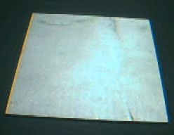
19.5X19.5cm Aluminum Base Plate
Motors and gears
Choosing motors with the appropriate gearing at first seemed very difficult. Here are three alternatives that were considered:
-
1)Motor with a custom build gear box.
-
This was probably the most costly and difficult to implement. It would take
extensive calculations, experimentation, and machine shop hours to produce
a well matched motor and gear box combination.
2)Gearhead motors
-
This seemed to be the most logically choice, but after going through many
catalogs and phone calls, This option was abandoned. The cost of gearhead
motors are very high and their torque range are limited.
3)Cordless power tools
-
In recent years cordless power tool's popularity has exploded. These tools
are compact, produces high torque, and because they are mass produced, their
price are very reasonable.
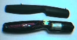
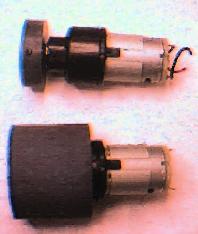
2.4V Cordless Screwdriver
Motors mounts
This proved to be somewhat of a challenge. The simplest way was to use the original housing from the cordless screwdriver and strap it onto the base with a hose clamp. This would have worked if the housing diameter was the same through its length. It was not the case with this unit, the housing is tappered.
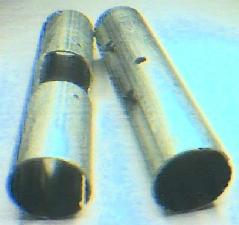
Another approach was chosen. A 1.5" galvanized cable conduit with an inside diameter (ID) of 1 3/8" was cut into 16cm length to house two motors (one on each end). The machining done was boring out .04" to increase the ID and cutting of two 1/8" slots on each end because the gear box is keyed. Boring to increase the ID can be avoided if 1.5" aluminum tubes or fence post with thinner walls were used. The cable conduit was selected because of its cost and availability.
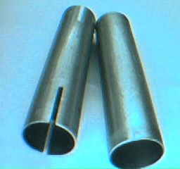
Finished and unfinished motor housings
Wheel Assembly
Since the motors put out tremendous amount of torque, a way of transferring this to linear motion is very important. The initial choice was RC car racing wheels. This proved to be a little too costly, plus, extensive modification to the hub was required. In this case it was more practical to design and build custom wheel assemblies.
The first thing was to decide on what kind of tires to use. After testing some rubber tires from toy cars and also considering making custom ones using silicon glue on a round tube, the rubber lint roller was discovered while looking through a Dollar store. It is a round rubber tube and very sticky. Unfortunately they were only about one inch in diameter. However larger version of this lint roller with an ID of 1 9/16" was found to be available in many hardware stores. The lint roller comes in 7" lengths and four 1.75" tire was made from one roller.
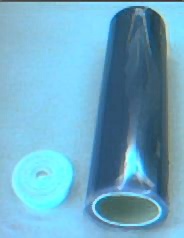
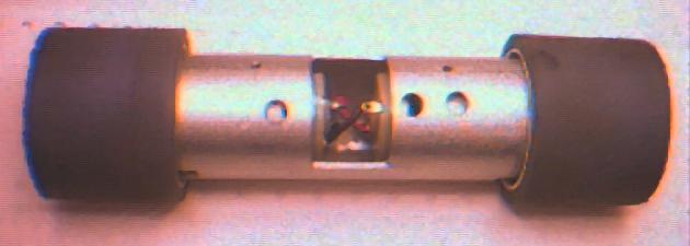
Lint roller, wheel, hub and motor assembly
Now, onto the hubs. This was custom made by the local machinist out of
PVC plastic. It is basically a 1 9/16" round disk friction fit into the tire
and a 12mm hole in the middle for the motor's output shaft. A set screw
was used to secure the entire wheel assembly on to the motor's output shaft.
For the do-it-yourselfers, the hub can be made from wood by using a hole
cutter on a drill press and the 12mm hole can be drilled out using a 12mm
drill bit. The set screw can be substituted with a regular wood screw of
the appropriate diameter and length. Just don't forget to pre-drill and
counter sink the hole for the wood screw to avoid splitting the hub.
Wheel and motor assembly
Base Assembly
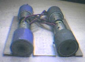
With all the mechanical components finished, it's time to put everything together. Initially, the wheel assemblies were to be mounted onto the base plate with hose clamps. To do this, slots had to be cut out (drill and file) on the base plate and the wheel assemblies are strap down with hose clamps. However following the advise of our local machinist two holes per motor mount were drilled and taped with corresponding holes drilled on the base plate to accept 6-32 countersink screws. This was a much better and cleaner solution.
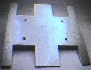
Finished motor mounts and base plate
Besides the holes on the base plate for the motor mounts, additional material on it had to be removed for the wheels. This was done with a hack saw, drill press and lots of filing. Also, openings on the motor mounts were made to pass wires for the motors.
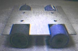
Base with wheels and motor assemblies mounted (Which way is up?)
This concludes the bulk of the mechanical work. There are still some more mechanical issues that have not been considered, such as mounting of the batteries, electronics and its armour. They will be addressed in another section of this document.