Procedure and Guidelines
for General Access Computer Labs Setup
1) Plan room layout, move tables to appropriate locations. Points to consider:
A) Close to power outlets to avoid running power cords where users walk.
B) Close to network jacks to avoid running networking cables where users walk.
C) Space between rows of tables. Single rows with one chair should have
at least 3 feet between. Back to back rows with users working back
to back should have at least 5 feet between tables.
2) Computer placement, try to place computers in groups and close to power and network outlets. This will facilitate the installation of the networking and fiber optic alarm cables.
Here are some examples of table and computer placement:
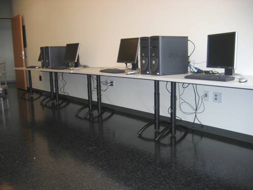
Computer Towers are grouped in two’s on tables along
the wall
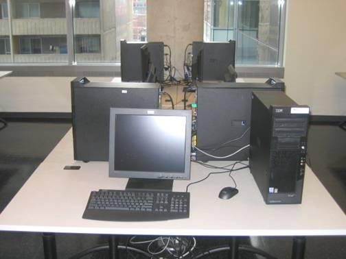
A group of three and two
IBM computers in the middle of a room
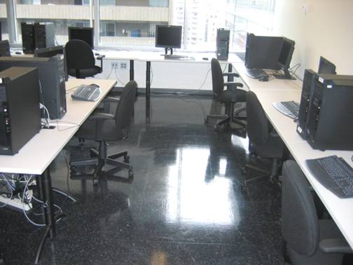
Last example of computer
and table placement
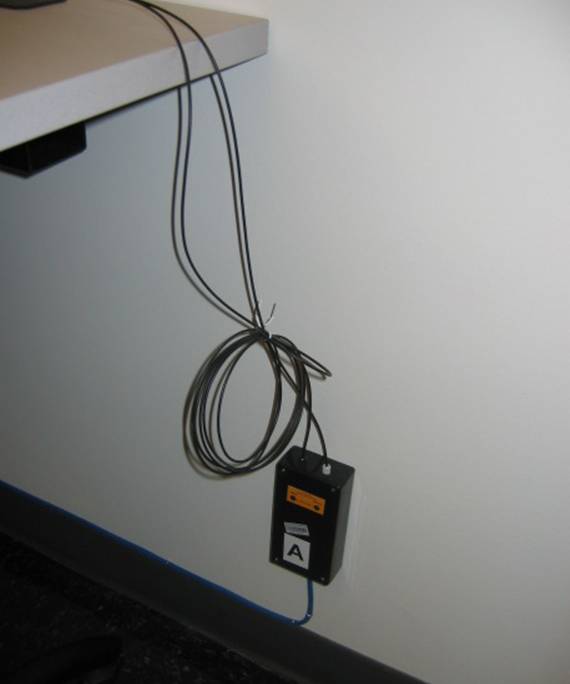
3) Fiber optic alarm transceiver placement, points to follow:
A) It should be placed at the end of a group of computers.
B) The height of its location should be about 8-12 inches below the table.
C) It should not be placed in a location where a user can get his or her foot on it.
D) It should be located close to a networking jack.
E) Transceiver boxes should be labeled A, B, C, D…, with the unit closest
to the door starting with “A”.
F) All transceiver boxes should use the highest patch number if there
is more than one connection on that wall patch.
Examples of transceiver placement:
Good placement of an old style transceiver, visibility
and access to the unit is ideal
Good example of a new style transceiver box placement
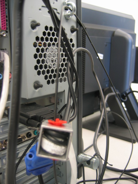
4) Securing the equipment
A) Keyboard, mouse and special video adaptor cables should go on a mouse
trap.
B) Small items such as speakers or webcams can be secured by using a
mouse trap on their power and/or other cables going to the computer.
C) Larger items such as scanners or printers will need a carried nut or “U”
bolt that can be solidly mounted on the equipment for the fiber optic cable
to pass through.
D) Monitors, only LCD flat panel monitors need to be secured. This will
vary depending on the model and make. The main idea is to have something
that is securely attached to the monitor for the fiber optic cable to pass
through.
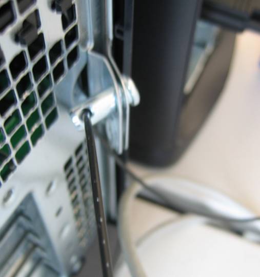
E) PC towers, the same idea as the LCD flat panel displays. However, IBM
cases are equipped with a lock which should be engaged to prevent unauthorized access to the internals of the computer. Dell computers have a
hole which a clevis pin is used to secure the computer case.
Examples of Dell and IBM computer systems:
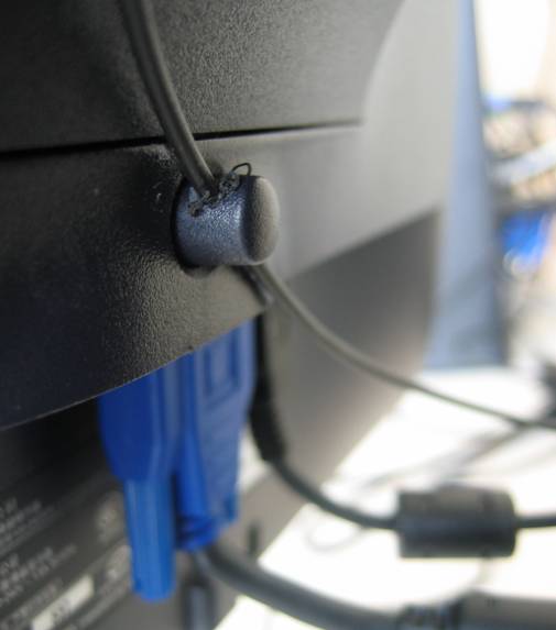
Dell Monitor with drilled out button for security
cable
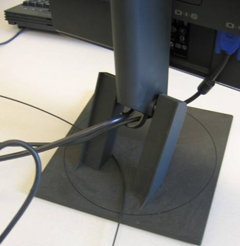
IBM monitor with fiber through base
5) Networking and fiber optic cable placement. This is where neatness counts.
A) All cables should be tucked into the tray under the table to ensure
users cannot get their foot tangled in it.
B) All long runs of cable should be stapled onto the wall or along the baseboard.
C) For fiber optic cables, ensure there will be enough slack on the monitors to
avoid false alarms because users will move them around and strain the
fiber cable if it is too short.
D) Networking cable has to be plugged into the computer’s networking port and
connected into the wall patch.
Good and not so good examples of running cables:
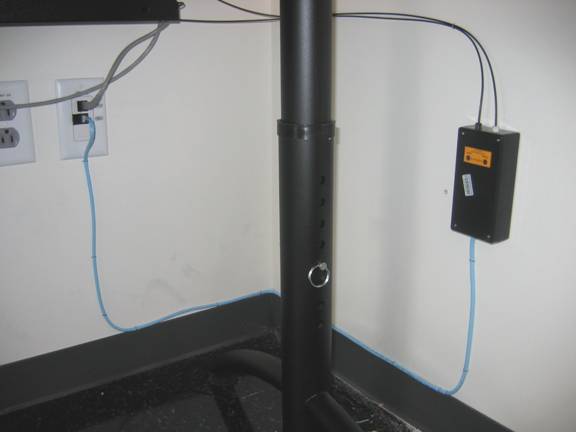
Excellent example, all cables are tacked, nothing
loose for user to get tangled on.
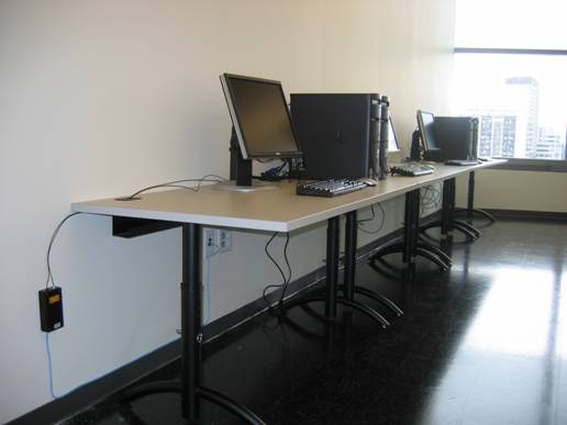
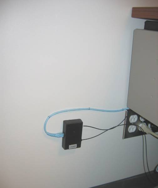
An acceptable example, the fiber optic cable placement
(could use more staples)
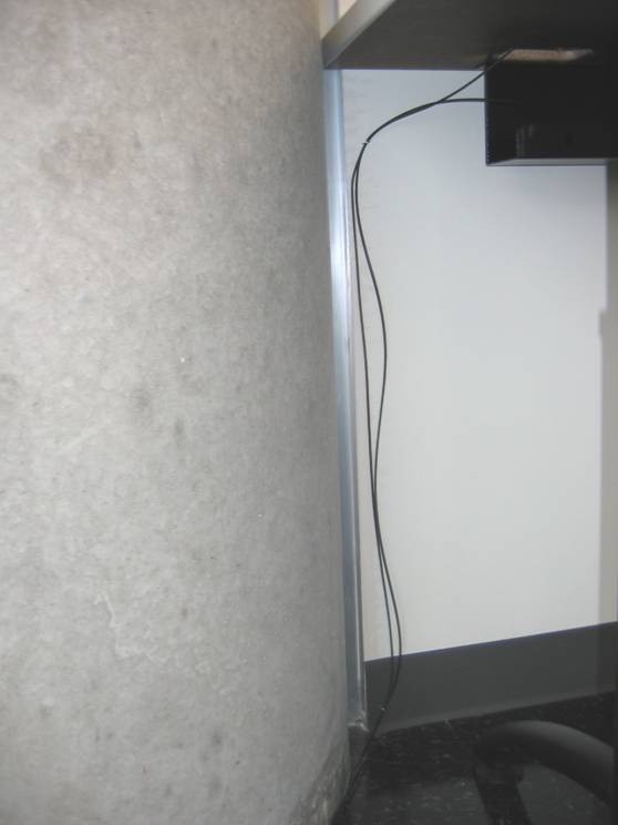
Not so good example, the fiber should be stapled onto
the wall
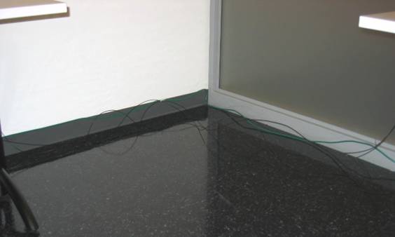
Bad example, cables should be stapled along the bottom
of the wall
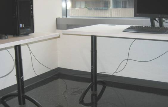
Another bad example, need more slack so cable can be
tacked along baseboard
6) Documentation, documentation!
A) Take note of all ENCS inventory tags per computer system.
B) Take note of all wall patch numbers for each computer and alarm transceiver boxes that they are connected to.
C) Take the information from A) and B) and inform Inventory and SAG via RT.
7) Required tools and components.
A) Alarm transceiver box old design:
Plastic wall plugs
#8 or #10 wood screws
Robinson and Philips screwdriver
Cat5 cable
RJ54 jack and crimper
Wire cutter and stripper
B) Alarm transceiver box, new design:
Double sided tape
Cat5 cable patch cord
C) Computer system:
Network patch cable
Staple gun
Mouse trap
Clevis pin for Dell towers
1/8” drill bit and drill for Dell monitors
“U” bolt and carried nut for IBM towers
Fiber optic security cable
Staple gun
Power bar if needed