Add.e.coli
abstract background objectives proposal methods risks summary refernences
Authors: Yao Zhang, David Colatriano,
Elio Bidinost for COEN691A: Synthetic Biology and Biological Computation 2011
Abstract:
In biological systems, cellular networks, which can be thought of as modular components that implement logic gates – underpin computation. Building complex systems from Boolean logic gates is fundamental to electrical engineering and circuit design. We present the design of a biological Full-Adder circuit, which is composed of three logic gates – a biological AND, OR and XOR. These three biological gates are combined to produce a Full-Adder circuit. We intend to show how these circuits may be evolved, and how they may be used to build larger biological circuits and networks. To perform the desired logic operations in these biological systems, biological substrates such as DNA, RNA and proteins are used as inputs, outputs and information processing hardware.
Background:
We propose to design a full-adder biological circuit. The full-adder biological circuit would be composed of three logic gates, a biological AND, OR and XOR. The biological AND, OR, and XOR are rather simple and limited in functionality [22], although, when combined the biological gates can be used as modular building blocks. The implementation of a full-adder, implemented with a biological AND, OR and XOR logic gates, in our project will represent a method for the future development of more complex biological circuits. We will use E. coli as a host organism for the full-adder gene network. E.coli is a gram negative prokaryote cell that is routinely used in a laboratory setting as a model organism -due to the fact that it is a highly characterised and easy to work with.
Boolean Logic – Full-Adder
In a general purpose computer a binary adder accepts two bit strings which represent numbers, and will produce a combined sum as output. Formally, a number “x” is represented as x = a0 a1 ...an where a0 a1 ...an is considered the bit string. A full-adder will then process the numbers x = a0 a1 ...an and y = b0 b1 ...bn bit by bit commencing with the left most bit. Each bit addition constructs a resultant digit for the sum, as well as, a carry digit for the next higher position. Therefore, a necessary sub component for the implementation of a full-adder is to design and build a half-adder. [18]
A half-adder is a simple functional digital circuit composed of two logic gates (the XOR and the AND gate). The purpose of the half-adder is to perform the addition operation on single binary digits. The half-adder accepts two single binary inputs and produces a two bit output, “S” (the Sum) and “C” (the carry). The more significant bit is “C”, which is the bit value that theoretically is carried over to the next addition of the next two bits in the bit string sequence.
In the half-adder there are three different combinations for the two bit output based on the four possibilities for input: In the first case, if both inputs are 0 then S = 0 and C = 0. In the second case, if one input is 0 and the other is 1 then S = 1 and C = 0. Finally in the third case, if both inputs are 1 then S = 0 and C = 1. The less significant bit “S” is the result of the XOR logical operation on the inputs, resulting in 1 only when exactly one of the operands is 1 and in all other cases is 0. The “C” bit is the outcome of the AND logical operation, which results in 1 only when both operands are 1 and 0 otherwise. The constituent gates in the half-adder operate in parallel, and therefore can be designed independently.
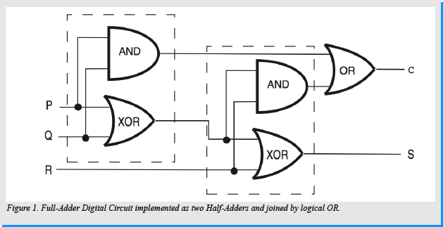
A full-adder circuit extends upon the functionality of the half-adder. The full-adder has not only the capability to add two binary digits, but more importantly is able to take into consideration the “C” (carry) bit: the significant bit from the output of the previous computation when computing the addition on the current 2 bit input. Consequently, a one-bit full-adder adds three binary digits, the inputs: “P”, “Q” and “R”. “P” and “Q” are the operands and “R” is the bit carried in. The full-adder circuit produces a two-bit output typically represented as “C out” and “S”. A possible implementation of a full-adder circuit is to construct two half-adder circuits and consequently join the outputs by an OR gate.
The first half-adder circuit takes “P” and “Q” as the input operands, and the XOR operation is performed to compute a preliminary sum. This sum is used as one of the 2 input operands to the second half-adder. The other input operand in the second half adder is “R”. The XOR operation is once again computed and the result is the final “S” as the output.
The final “C out” output of the full-adder is computed in the following way: First: a preliminary “Ci” is computed through the AND logical operation on the “P” and “Q” inputs in the first half-adder. Secondly: a “Cii” is computed through the AND logical operation between “R” input, and the result of the XOR operation between the “P” and “Q” inputs. Finally, the “C out” output is computed as the result of the OR operation on the “Ci” and “Cii” inputs. [Figure 1]
As a Finite State Automaton, the active full-adder needs to retain the “C out” bit in order for it to be received by the “R” bit of the consequent full-adder circuit. This is achieved by the circuit being in 1 of 2 states: the CARRY state or the NO CARRY state. Initially the circuit will be in the NO CARRY state, and it will remain in this state until the resultant “C out” bit is 1. The presence of this bit will trigger the circuit to transition into the “CARRY” state. In this state, the circuit will take into account the “Cout” bit when the next addition is computed. [Figure 2] Boolean computation can be implemented using circuits formed by interconnected cells, in which each cell responds to different input stimuli either activating or inhibiting the expression of a given output whilst retaining a state. [21]

Far Red Light Receptor Cph8
Bacteria primarily rely on the His-Asp phosphorelay signal transduction system (HAP system).
[1] One of the most extensively studied HAP systems is the EnvZ/OmpR system mediating signal transduction in E.coli. [2-4] EnvZ is a histidine kinase/phosphatase in E.coli, which will respond to the osmolarity changes in the medium by regulating the phosphorylation state of the transcription factor OmpR. OmpR controls the expression levels of outer membrane porin proteins OmpF and OmpC. When the phosphorylation of OmpR molecules are at low level, it will activate the expression of OmpF, whereas phosphorylated OmpR molecules at high levels will promote the expression of OmpC and to repress the expression of OmpF.
E.coli will not respond to the light naturally, so the chimaeric Cph8 is used as light receptor. Cph8 contains photoreceptor Cph1, phycocyanobinlin(PCB), EnvZ-OmpR. Cph1 is a light-regulated histidine kinase which trans-phosphorylates a response regulator. After assembly with the natural chromophore phycocyanobilin (PCB), the component will respond to far red light. [5] As a result, when far red light is turned on, the autophosphorylation will be inhibited, which will activate the OmpF promoter.
UV Light and SOS Response
The SOS response system is a complex regulatory scheme in which the products of two genes, recA and lexA control the expression of a number of other genes involved in DNA repair. We used one of these gene’s promoter – uvrA. The genes of the SOS response are ordinarily maintained in an “off” state. This is accomplished by the lexA gene product, the LexA repressor, which binds to an operator sequence near each gene and prevents its transcription.
When E coli is subjected to UV light, it will turn on the SOS response system. The RecA protein will be activated and will interact with the LexA repressor protein, stimulating the LexA repressor to inactivate itself by proteolytic cleavage. With the repressor inactivated, all of the genes involved in the SOS response can be expressed -here we use the uvrA promoter.
Plasmids
For our design, we use the CRIM plasmids that were developed by Anderas Haldimann and Barry
L. Wanner in 2001. CRIM is an acronym for a series of powerful and versatile Conditional-Replication, Integration, and Modular plasmids. We choose these plasmids for several reasons. [6] First of all, as normal plasmids, CRIM plasmids can be high copy in E.coli cells, which is the base of our network. Secondly, since our design is complex, we need at least four plasmids, each plasmid needs different kind of antibiotic resistances, because we have to make sure that all the genes that are necessary for the network are transformed to the cell successfully. CRIM plasmids can encode different forms of resistance, several can be used together in the same cell for stable expression of complex metabolic or regulatory pathways from diverse sources. [6] Lastly, the CRIM plasmids can be integrated a single copies into the chromosomes of E.coli and related bacteria to study gene function under normal physiological conditions.
The chosen four CRIM plasmids: pAH143 2.1kbp (gen resistance), pAH 144 2.5-kbp (aadA resistance), pAH68 2.4kbp (bla resistance) and the pAH143 2.1kbp again -but we would replace the gen with a kan resistance marker, and we will use Ptet as promoters for all these plamids.
Recombination Switches
The recombinases will bind to these two sequences which are recombinase specific. After binding, the DNA will be cleaved. The reaction can end up by the coding sequences being be cut out, or the DNA can switch orientation then ligated back. In this case, the sequences switch orientation, which means that the coding strand is now the non-coding strand.

There are several advantages to using site-specific recombinases. First of all, it has binary dynamics. The state will be either on or off. As we mentioned before, if the coding sequences are on the right orientation, the state will be on, if the coding sequences are switched, the state will be off. When comparing site-specific recombination to using repressors to control the gene expression, we see that using recombinases will avoid the leakage problem of repression. Also, we decrease the chance of the cross talk -which is hard to avoid with synthetic networks. As we use different recombinases, they will only bind to their specific sites. In the development of our full-adder system we use three different recombination systems.
Cre-lox system
This system is composed of a 38-kD phage-encoded Cre recombinase that mediates symmetrical recombination between two 34-bp loxP sites [7], which are recreated after recombination. Recombination between two compatible loxP sites will excise or invert the intervening DNA.
Hin-hix system
In this system, the Hin DNA recombinase catalyzes the inversion reaction. The asymmetrical sequences hixL and hixR are the invertible DNA segment and serve as the recognition sites for cleavage and strand exchange. [8] Further study shows that Rather than hixL and hixR, hixC, a composite 26 bp symmetrical hix site that shows higher binding affinity for Hin and a 16-fold slower inversion rate than wild type sites hixL and hixR. [9] So in our network, we choose hixC for binding and excising and hixL for binding and inverting.
Flp-FRT system
The FLP system has been well studied. People prefer to use this system because of its efficiency and simplicity. The only requirements for FLP recombination are the FLP protein and the FLP recombination target (FRT) sites on the DNA substrates. The minimal functional FRT site contains only 34 bp. The FLP protein can promote both inter-and intramolecular recombination [10].
Cell-cell communications
Gram-negative bacteria often use acyl homoserine lactones (AHLs) as communication signals.
[11] These AHLs are typically synthesized by Lux-type enzymes and diffuse freely across bacterial cell membranes. AHL signals often lead to activation of cytoplasmic regulator proteins, which then activates target gene expression. In our design, we use two well known pairs. First is that the cytoplasmic transcription factor LuxR recognizes LuxI and activates gene expression of the well characterized luxI promoter. Therefore, the expression of PluxI will be regulated by the specific AHL. Second is that LasR + LasI AHL will be recognized by activate the LasI promoter. We use different AHLs as carry-outs and different promoters to recognize the AHLs as carry-ins. As a result, each strain will produce a different AHL that will only give signals to one other strain and have a different carry-in promoter that will only act when receiving a certain AHL signal.
Objectives:
In order to approach the design and implementation of the biological circuit – the full-adder, we set forth several objectives, that if successfully completed would lead to a fully operational full-adder biological circuit and network.
a) Research the current work being done on cell-cell communication and distributed processing techniques in biological computation i.e. Boolean logic gate modelling at cellular level.
b) Implementation of a Full-Adder biological circuit, which is itself composed of two Boolean logic circuits – the Half-Adder. The Half-Adder, is itself composed from Boolean logic gates, the logical AND and logical XOR. Furthermore, we would need to design an additional Boolean logic gate which completes the Full-Adder – the Boolean logic OR gate.
c) Research and test implementation of full-adder circuit and network system, ensure that the Boolean logic circuits support the expected outcome.
d) Implementation of a full-adder circuit and network, ensure that the cell-cell communication (AHL) and computation over a larger network of interconnected cells compute the desired results.
Proposal:
Efforts within synthetic biology have been directed towards the assembly of biological computational devices, these devices, at the core, implement Boolean Logic gates which act as the primary units of basic modular building blocks. A majority of these efforts are inspired by the design of digital electronics circuits. However, these designs are limited by difficulties which arise from “wiring” these basic modular building blocks through the appropriate connections and targeted molecules. [19]
Our group proposes to build a network of E. coli full-adders that use UV and Far Red Light as inputs in such a way as to add binary numbers. We would like to show a different form of implementing complex Boolean logic computations that may potentially reduce the “wiring” constraints of previous efforts by the distribution of desired output among our engineered E.coli network of full-adders. For the initial implementation and proof of concept we have decided to engineer a library of E.coli cells that can act as part of a semi-distributed network system. Each E.coli cell defines the Boolean logic to implement a full-adder (single-cell implementation), and by cell-cell communication protocol -this will allow us to build more complex synthetic devices. [20]
The small library of engineered cells will have restricted connections among themselves, and each cell will have the ability to respond to up to three inputs (FRL, UV or Carry-In), and provide a desired output. The output of each cell is always a desired output being either GFP, a AHL molecule or both. In our system, we have not used cell-cell feedback, instead cells respond only to external input and to a diffusible (AHL) molecule acting as desired input. The computation is determined by the location of the cell in the network. [22][21]
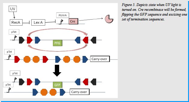
In this system, there are two inputs. These inputs are UV light and Far Red Light (RL). In the diagram above, we can see that when E. coli is exposed to UV light, it will turn on the SOS response, which turns on the expression of RecA. Certain promoters involved in the SOS response are suppressed by the suppressor LexA under normal conditions. When RecA is produced, it acts as a co-protease to help with the self-cleaving of LexA, removing it from performing its repressor function. The UVrA promoter is one such promoter and is quickly activated in the presence of UV/RecA. [16]
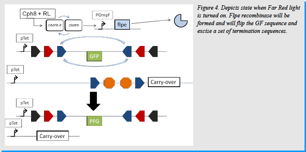
In the case of Far Red Light, we used the photoreceptor Cph8, created by the UTexas iGEM team in 2004. [14] This is a fusion of Cph1 (cyanobacterial light sensing phytochrome), EnvZ (E.coli transmembrane histidine kinase) and PCB. OmpR, which is normally phosphorylated, interacts with Cph8 when in the presence of Far Red Light and is dephosphorylated. If dephosphorylated OmpR will activate the OmpF promoter. On the other hand, when the Red Light is turned off OmpR stays phosphorylated and does not act on the OmpF promoter making transcription not possible. [12] [Figure 4]
The output signal we chose to use was Green Fluorescent Protein (GFP). If the output signal is 1, it will be represented by the production of GFP. If the output signal is 0, it will be represented by the absence of green fluorescence.
The input signals we used, as mentioned above, are UV and Far Red Light. For the UV input, a 1 would be represented by turning ON UV light and shining it onto the cell. 0 is represented by not shining the UV light onto the cells. In the case of Far Red Light, a 1 is represented by turning ON the Red Light and a 0 would be represented by not turning on the light.
In some cases a carry-out signal will be produced and passed to the next adder. This signal will be expressed as an AHL and will differ for every adder. The AHL will also be specific for a promoter in the next full-adder in the chain. In this way the carry-out signal will only affect one other cell in the chain and not all the cells. An example of this would be a carry-out signal of LuxR and LuxI matched with a LuxI promoter.
The way this system works is through the action of recombinases. If the recombinase Cre is produced, it will invert everything within the LoxP sites on the gene fragment containing the GFP since the LoxP sites are positioned so that they are facing each other. [15, 17] It will also excise the termination sequences between the two LoxP sites on the carry-over strands as the LoxP sites are going in the same direction. [15] The flpe and Hin recombinases work in the same way with their recombination sites, FRTf and HixL/C respectively. If only one recombinase is made the GFP sequence will be inverted so that it is now in the same direction as the promoter. This enables GFP expression. If two recombinases are produced, the GFP sequence will be inverted twice, returning to the inactivated wrong direction. If three recombinases are produced the GFP sequence will be inverted 3 times so that it ends up with the GFP facing the same direction as the promoter and will thus be expressed.
In the case of the carry-over signals, if only one recombinase is made, only one section of termination sequences will be
removed and thus the carry-over AHL will not be produced due to the second set of termination sites. If two recombinases are produced the carry-over molecule will be produced since one of the three carry-over producing cassettes will be free of both sets of termination sequences. If all three recombinases are produced then the carry-over AHL will be produced because all three termination regions will be excised. Examples of AHL/promoter systems are LuxR+ LuxI as an AHL and the LuxI promoter as the specific promoter in the next strain and LasR+ LasI as AHLs and Plas as the inducible promoter in the next strain.
Thus, we can represent the numbers we wish to add as tw binary numbers and add them using this system as we would a full-adder. As an example let us take the numbers 3 and 1 and add them together. The number three is represented as “1 1” in binary code and the number 1 is represented as “0 1”.
As with regular addition, we move from right to left to solve the problem. We will use UV light to represent the number 3 and Far Red Light to represent the number 1. The expected value would be 4 or, 1 0 0 in binary. To do this addition we would need a total of three wells connected to each other by a filter. This ensures that the AHLs can pass freely from one strain to another, but the E. coli themselves stay in their respective wells. Moving from right to left we can see that the first well should have an input of 1 for the UV as well as an input of 1 for the Far Red Light. UV light will turn on the cell’s SOS pathway, making it produce RecA. RecA will bind to LexA and help cleave it, thus activating the UVrA promoter.
Once the UVrA promoter is active, Cre recombinase will be made. It will then bind the LoxP sites in the system. This will cause a recombination event that will flip everything between the two sites on the GFP plasmid, making GFP face the right way. Cre will also excise everything between the LoxP sites in the carry-over plasmids. [Figure 5] At the same time Cph8 will recognize the Far Red light. EnvZ will interact with OmpR-p, dephosphorylating it to OmpR. OmpR will then activate the OmpF promoter. This will cause the production of the flpe recombinase. Flpe will bind to the FRTf sites in the pathway. It will cause everything within the sites on the GFP plasmid to flip. Because GFP was already oriented the correct way due to the Cre recombinase, it now gets re-oriented in the reverse (improper way). It will also cause everything with the FRTf sites on the carry-over plasmids to be excised. In doing so it releases one plasmid of all termination signals allowing the carry-over molecule to be produced. [Figure 4]

As we can see in the [Figure 6], because two recombinases were made, the GFP is put back into the wrong orientation. This leads to no GFP production and thus an output signal of 0. On the other hand, because two recombinases were made the carry-over molecule is made. This molecule will be exported from the cell and through diffusion in the media interact with the next cell in the system. In the next cell, there is an input of 1 for UV and an input of 0 for Far Red Light and there is also a carry-in input. In essence, a similar process as above is produced but instead of flpe acting on the FRTf sites, Hin will act on the Hix sites. [Figure 7]
This leads to no GFP production, but it does lead to the production of a carry-over molecule. This carrier molecule will be different than the first and will be specific for a promoter in the next strain in the network. This final strain will inputs of 0 for UV and 0 for Far Red Light. In this case the Cre and flpe recombinases will not be produced. Thus the only thing acting on the cell will be the carry-over molecule which will induce the production of Hin recombinase. Hin will flip the GFP between the two HixL sites and will cause GFP to face the correct direction and be expressed. Hin will also excise the terminator sequences between the two HixC sites. Because of the second set of termination sequences on each plasmid, the carry-over molecule will not be produced. [Figure 8]
All together, from left to right, the output will look like green fluorescence, no green, no green. This is the same as 1 0 0 which is what we expect. The number of adders one wishes to put together is at the user’s discretion. The only thing they would have to do is change the AHL/carry-over signal and carry-in promoter so that each strain is different.

We also acknowledge the fact that the container in which we would put these cells might have to be made as there is none on the market at the moment. This container would have to be able to have several wells, or reservoirs to accommodate the adder strains with their medium. Each well or reservoir would then have to be connected one after the other via a filter. This would allow the medium with AHLs to diffuse through, but not the cells themselves. This apparatus need only be available for performing addition with the adders. If the strains are being used as discrete components in a distributive processing type of pathway then there is no need for the special container.

Methods:
To create the full adder one must use 4 separate plasmids. This is due to the fact that we do not want unexpected recombination events due to the recombination sites. One plasmid will contain the GFP cassette as well as the Cph8 gene. A second plasmid will contain the flpe recombinase cassette with the OmpF promoter as well as the carry-over molecule cassette with the pTet promoter and the LoxP and FRTf recombination sites with two termination sequences between each set of recombination sites. The third plasmid will contain the Cre recombinase cassette with the pUVrA promoter as well as the carryover molecule cassette with the pTet promoter and the LoxP and HixC recombination sites with two termination sequences between each set of recombination sites. The fourth plasmid will contain the carryover cassette containing the Hin recombinase with the promoter for a specific AHL as well as the FRTf and Hix C recombination sites with two termination sequences between each set of recombination sites.
Each plasmid will have a different antibiotic resistance gene to act as markers, only allowing the cells that contain all four plasmids to live. The plasmid backbones we have decided to use are pAH143 2.1-kbp which confers gen resistance, pAH 144 2.5-kbp conferring aadA resistance, the pAH68 2.4-kbp confering bla resistance and the pAH143 2.1-kbp again, replacing the gen resistance marker with a kan resistance marker. [13] The antibiotic resistance gene for tetracycline will not be used as our constitutive promoters are tet promoters and would thus be repressed in the presence of tetracycline. An example plasmid map is depicted in [Figure 9].
To construct the plasmids we would use the yeast genome assembler technique. To do this we would first have to PCR-out the promoters’, GFP, Carry-out AHL, recombinases, and the Cph8 gene (biobrick BBa_I15010). The recombination site sequences can be found on the NCBI database and synthesized. I would then PCR-on homology regions to the PCR products. The homology regions will be as follows:
For the GFP/Cph8 plasmids, there would need to be homology between the tet promoter and the plasmid as well as between the tet promoter and the HixL recombination site. There will need to be a homology region between the Hix site and the LoxP site as well as between the LoxP site and the FRTf site. Please note that using these different homology regions we can orient the recombination sites so that they face the same way as the promoter. There will need to be another homology region between the FRTf site and the end of the GFP gene. This will ensure that the GFP gene is in the wrong orientation to begin with. There will also need to be homology regions between the front of the GFP and the front of the second FRTf site, the back of the FRTf site and the front of the second LoxP site and the back of the second LoxP site and the front of the Hix site. The Cph8 site would then be inserted after the Hix site. This method ensures that all the recombination sites are in place, the GFP is between all of them and facing the wrong way to be expressed, but Cph8 is facing the correct way to be expressed. For this plasmid to be made using yeast in vivo genome assembly, it would most likely take at least 2 rounds of assembly as there are many homology events that need to take place. The other 3 plasmids would be made in the same way, with the homology regions ensuring that everything is facing the appropriate orientation.

Once all four plasmids are constructed, they will be transformed into E.coli to produce our strains. We would grow the E .coli in medium containing all four antibiotics that the plasmids confer resistance to in order to ensure that all four plasmids are taken up by the host cell. These strains will then be separated into their respective wells or reservoirs. To test and validate our system, we would choose two binary numbers to add and try to add them using UV and Far red light as inputs. We would most likely start by testing one full-adder by giving an input of 1 and 0 and looking for GFP production. Then 1 and 1 and looking for the lack of GFP production. If this works, we would introduce multiple adders to see if the system works in a network (if the AHLs are being produced and recognized by the next cells in line).
Risks:
There are certain risks associated with this type of system, these include risks associated with recombination sites spontaneously excising, cross-talk between different recombination sites and recombinases, leaky expression of the AHLs, inadequate yield of the GFP signal or AHL signal molecules and cell-cell communication requirements.
As far as spontaneous excisions, if this does turn out to be a problem, we would try different recombination sites and recombinases. This would also answer the problem of cross-talk between the different recombinases and recombination sites. We could also mutate either the recombination sites or recombinases themselves to get them to be more specific for their respective counterparts.
Inadequate production of AHLs or GFP can be resolved by optimizing for a better promoter, or a better distance from the promoter. Although the 2 sets of termination sequences we have in place should eliminate the leaky expression of the AHLs, our solution to this problem would be to add more termination sites before the AHL gene.
Issues which relate to the induction of the pathway using the UV and Far Red light inputs. The ideal induction time for both inputs would have to be optimized as too much UV will be detrimental to the cell and too little will not induce the pathway. Similarly, not enough time with Far Red Light on will prevent the induction of the system. To solve these problems, we would need to optimize the time of exposure so that the system has enough time to emit the GFP signal and the AHL signal if it is supposed to.
As the circuit grows in complexity, as with our engineered E.coli full-adder (single-cell implementation), cell-cell communication requirements increase in proportion. The increase in cell-cell communication requirements limits the combinatorial potential of the constructs. [19]
Summary and Conclusions:
In the future we would try to find applications other than addition for the adders we have made. This would require different methods of differentiation techniques. These methods of differentiating between the individual adders would vary depending on the application we are using these E. coli for. For instance, different strains will emit different coloured fluorescent proteins as a signal molecule, or, depending on the inputs they receive from their surroundings and the cells around them they could output something other than a fluorescent protein that could drive a reaction in a cell that performs another type of Boolean logic function.
Referneces:
[1] Hoch, J. A. (2000) Curr. Opin. Microbiol. 3, 165–170
[2] Egger, L. A., Park, H., and Inouye, M. (1997) Genes Cells 2, 167–184
[3] Pratt, L., and Silhavy, T. J. (1995) in Two-component Signal Transduction.(Hoch, J., and Silhavy, T. J., eds), pp. 105–107, American Society for Microbiology Press, Washington, D. C.
[4] Forst, S. A., and Roberts, D. L. (1994) Res. Microbiol. 145, 363–373
[5] Lamparter T, Esteban B, Hughes J. Phytochrome Cph1 from the cyanobacterium Synechocystis PCC6803. Purification, assembly, and quaternary structure Freie Universitaet Berlin, Pflanzenphysiologie, Germany.
[6] Haldimann, A., Wanner, B. L., Conditional-Replication, Integration, Excision, and Retrieval Plasmid-Host Systems for Gene Structure-Function Studies of Bacteria, JOURNAL OF BACTERIOLOGY,2001,Nov. 2001, p. 6384–6393
[7] Abremski K and Hoess R. Bacteriophage P1 site-specific recombination. Purification and properties of the Cre recombinase protein. J Biol Chem 1984 Feb 10; 259(3) 1509-14. pmid:6319400.
[8] Haynes KA, Broderick ML, Brown AD, Butner TL, Dickson JO, Harden WL, Heard LH, Jessen EL, Malloy KJ, Ogden BJ, Rosemond S, Simpson S, Zwack E, Campbell AM, Eckdahl TT, Heyer LJ, and Poet JL. Engineering bacteria to solve the Burnt Pancake Problem. J Biol Eng 2008 May 20; 2 8. doi:10.1186/1754-1611-2-8 pmid:18492232.
[9] Lim HM, Hughes KT, and Simon MI. The effects of symmetrical recombination site hixC on Hin recombinase function. J Biol Chem 1992 Jun 5; 267(16) 11183-90. pmid:1597453.
[10] Huang LC, Wood EA, and Cox MM. Convenient and reversible site-specific targeting of exogenous DNA into a bacterial chromosome by use of the FLP recombinase: the FLIRT system. J Bacteriol 1997 Oct; 179(19) 6076-83. pmid:9324255.
[11] Lazdunski AM, Ventre I, Sturgis JN: Regulatory circuits and communication in Gram-negative bacteria. Nat Rev Microbiol 2004, 2:581-592.
[12] Cai, S. J., and M. Inouye. 2002. EnvZ-OmpR Interaction and Osmoregulation in Escherichia coli. Journal of Biological Chemistry 277:24155-24161.
[13] Haldimann, A., and B. L. Wanner. 2001. Conditional-Replication, Integration, Excision, and Retrieval Plasmid-Host Systems for Gene Structure-Function Studies of Bacteria. J. Bacteriol. 183:6384-6393.
[14] Levskaya, A., A. A. Chevalier, J. J. Tabor, Z. B. Simpson, L. A. Lavery, M. Levy, E. A. Davidson, A. Scouras, A. D. Ellington, E. M. Marcotte, and C. A. Voigt. 2005. Synthetic biology: Engineering Escherichia coli to see light. Nature 438:441
442.
[15] Nagy, A. 2000. Cre recombinase: The universal reagent for genome tailoring. genesis 26:99-109.
[16] Slonczewski, J. L., and J. W. Foster. 2009. Microbiology An Evolving Science. Norton, New York.
[17] Zhang, Z., and B. Lutz. 2002. Cre recombinase mediated inversion using lox66 and lox71: method to introduce conditional point mutations into the CRE binding protein. Nucleic Acids Research 30:e90.
[18] P. Linz, An Introduction to Formal Languages and Automata. Sudbury, Mass.: Jones and Bartlett Publishers, 2006.
[19] J. C. Anderson, C. A. Voigt and A. P. Arkin, "Environmental signal integration by a modular AND gate," Mol Syst Biol, vol. 3, 08/14, 2007.
[20] S. Basu, Y. Gerchman, C. H. Collins, F. H. Arnold and R. Weiss, "A synthetic multicellular system for programmed pattern formation," Nature, vol. 434, pp. 1130-1134, 04/28, 2005.
[21] N. E. Buchler, U. Gerland and T. Hwa, "On schemes of combinatorial transcription logic," Proceedings of the National Academy of Sciences of the United States of America, vol. 100, pp. 5136-5141, April 29, 2003.
[22] S. Regot, J. Macia, N. Conde, K. Furukawa, J. Kjellen, T. Peeters, S. Hohmann, E. de Nadal, F. Posas and R. Sole, "Distributed biological computation with multicellular engineered networks," Nature, vol. 469, pp. 207-211, 01/13, 2011.
[23] A. Tamsir, J. J. Tabor and C. A. Voigt, "Robust multicellular computing using genetically encoded NOR gates and chemical /`wires/'," Nature, vol. 469, pp. 212-215, 01/13, 2011.