Lab #2
In this lab a
light sensor and a servo motor actuator is combined with an Arduino. This allows the Arduino to move the servo
motor to a desired angle and to measure incoming light.
Sensors
and actuators
A sensor
is a device used in a mechatronic system in order to measure some quantity in
the system (e.g. position). An actuator
is a device used to change the system (e.g. a DC motor). The sensors are analogous to the five senses
of a person and the actuators are like the muscles and limbs. Actuators and sensors normally have
electronics (combined or sold separately) to interface with a
microcontroller. The microcontroller can
be programed to read the sensors and based on this information decide how to
change/write the actuators. This gives
the mechatronic system the capability to react to its environment and
accurately control its response.
In this lab a
Hitec HS-422 servo motor is used (see the following datasheets).
http://www.robotshop.com/media/files/pdf/hs422-31422s.pdf
http://www.robotshop.com/media/files/pdf/servomanual-31422s.pdf
A hobby servo
motor (such as the Hitec HS-422) also has built in controller plus amplifier
electronics that adjust the voltage of the DC motor in order to achieve the
desired position (sent from the Arduino).
The servo receives a digital output signal from the Arduino in the form
of a pulse (i.e. a 5 V / high signal) every 20 ms. The pulse width indicating the desired
position varies from 1 ms (0 deg) to 2 ms (180 deg) (see figure below). The exact range of pulse width depends on the
model.

The Arduino
is capable of generating such pulses using a servo library function. The user simply has to call the servo
function with the desired angle. It
should be noted that the details of a servo as indicated above are not
essential to the lab. The user can
simply consider the servo as a device that attempts to go to a desired position
set by an Arduino servo function.
Servo
actuators are useful for moving / positioning parts in a mechatronic system
such as robot links and robot wheels (if suitably modified for continuous
rotation). Servos come in a wide variety
of sizes, torque capacities, and speeds.
They are also available with different gear types (nylon, metal,
Karbonite, titanium, etc.). Other types
of actuators such as brushless motors used in flying drones also use a servo
type pulse interface.
Lab Tip: Hitec HS-422 servo motors can be easily
modified for continuous rotation (i.e. rotation beyond the normal 0 to 180 deg
range). This allows them to be used for
wheels in a mobile robot. You can modify
your motors after Lab #3 if needed when making your robot (if you need wheels
instead of arms). More details will be
provided in Lab #3.
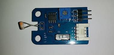
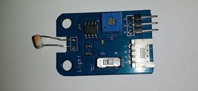
The light
sensor used in this lab is the iTead Studio Electronic Brick Light Sensor (see
datasheet and wiki below)
ftp://imall.iteadstudio.com/Electronic_Brick/IM120710017/DS_IM120710017.pdf
https://www.itead.cc/wiki/Light_Sensor_Brick
This type of
sensor produces an analog (i.e. continuous) voltage that changes depending on
the amount of incident light. The
voltage varies continuously from 0 V to 5 V.
It can be read using an analog input pin on the Arduino with the analog
read library function.
Light sensors
are typically used for obstacle detection (light is blocked when close to
another object) and distance measurement.
In order to measure distance a light source is needed. This light source can be mounted on a target
object to measure its distance as shown in the lab example. The light received will vary depending on the
distance. The relationship will not be
directly proportional, but it can be calibrated using another sensor such as a
measuring tape.
Wiring /
connecting the components to the Arduino
Electronics is beyond
the scope of this course,
but a certain amount of wiring is needed in order to connect the components to
the Arduino. Just carefully follow the
wiring instructions below. However,
students should try to remember the good wiring practices and tips discussed in
this lab since they will be useful in the future and possibly save you money.
Wiring is a
necessary evil with mechatronics, but it should be taken seriously. Incorrect wiring can damage your equipment
(especially the Arduino), produce incorrect/inconsistent programming results,
and waste a lot of time later on. Always
check your wiring first before continuing with the programming task (or
looking for programming errors) since you can waste a lot of time looking for
programming errors when the actual problem is wiring (incorrect wiring, loose
wires, cables not connected, power not connected, etc.). This advice is especially applicable to
students without much electronics experience since rookie errors are very
common at first.
The jumper
cables and block connectors (a.k.a. lever nuts) included in the Arduino Lab Kit
considerably simplify the wiring process and avoids the use of a soldering
iron, although some wire cutting / stripping is required. The 5V power supply (Sparkfun Wall Adapter)
wires, for example, must be stripped (and the USB connector cut off) as
indicated in the following picture.

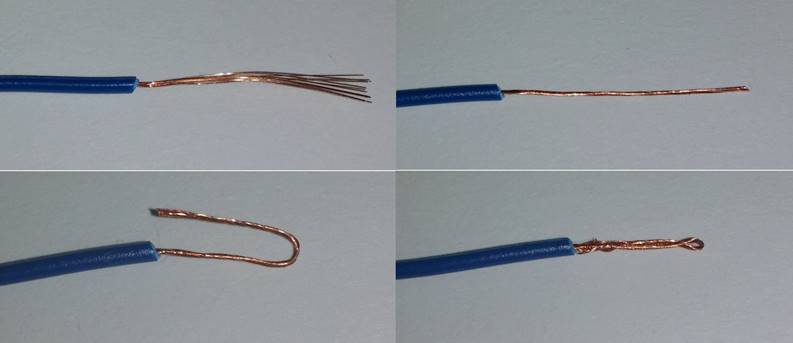
Note that a
striped wire end/lead should normally be twisted to provide a good connection
and help prevent fraying. For example,
the leads of the power supply are striped and twisted as follows (see figure
above). Note you should be very careful
not to partially cut some of the wire strands by squeezing the wire cutter /
stripper too hard – these partially cut wires will eventually break off.
Lab Tip: You should inspect the outer wire strands to
look for signs of accidental cutting after stripping. Wires with accidental cutting tend to fall
off over time and can cause a lot of problems.
If this occurs then snip off the end and try again. This also applies to removing the outer wire
insulation containing both the red and black wires.
Lab tip: It’s normally a good idea to practice wire
stripping using the end of the wire or some spare wires until you learn how to
do it without damaging the wires.
Different types of wire will require different practice.
Care should
also be taken when stripping off the outer insulation that surrounds the black
and red wires inside. Don’t press the
cutters too hard – it sometimes helps to rotate the cutters 360 degrees when
pressing before pulling the outer insulation off.
Lab tip: It pays to be careful with wiring in general
for mechatronics projects. Your
equipment could be damaged and your program won’t work if the wiring is
wrong. It can be very difficult to find
wiring errors because they can look like programming errors or equipment
malfunctions. I always triple check my
wiring before proceeding with programming.
This includes obvious things such as connecting the power supply to the
outlet and the Arduino to the USB port.
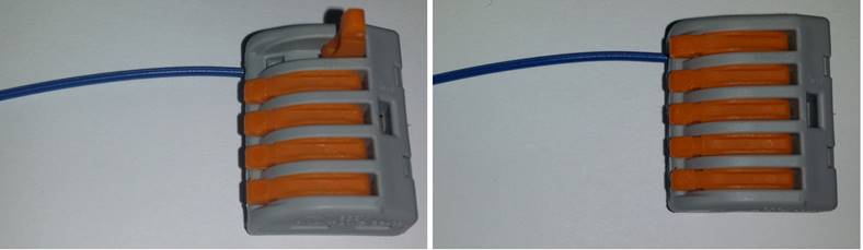
Lever nuts
are used in the lab to connect multiple input wires together. This is basically the same thing as twisting
all the wire leads together and soldering them but without the fuss. Another advantage is that the input wires can
easily be removed and re-connected (see figure below). Further, the current rating is much higher
than the pins and sockets of the jumper wires since the connection is much
tighter. Note that the lever nuts
included in the kit have 5 inputs. If
you need more inputs then just twist two of the input wires together and insert
into one of the inputs.
Note that you
should never just twist wires together to make a connection without using
solder since this can lead to intermittent connections that can play havoc with
digital devices such as the Arduino.
Lab Tip: In
order to insert a wire the lever has to be at 90 degrees as shown in the above
figure. You have to pull the lever
fairly hard to open it.
There is a
minimum wire diameter that can be connected to a lever nut. The jumper wires included in the kit are a
bit smaller than that minimum diameter.
This problem can be solved by bending the wire backward and twisting it
in order to make a double thickness wire end (see the figures below). Note the wire in the final picture of the
series probably should have been twisted more.
There are two
types of jumper wires included in the lab kit, namely female / female and
female / male. Note that one of the
female connectors can be removed with a wire cutter if you need an extra jumper
with one end connected to a lever nut.
Also note that a male pin can be inserted into a lever nut input.
At this point
you can wire the components to the Arduino.
An illustration showing the connections is given by the picture below.
Please refer to the Arduino picture from Lab #1 in
order to clearly see the location of the Arduino pins (pin 7, A0, etc.).
Lab Tip: Always disconnect the power supply and the
Arduino from the USB port of the PC (i.e. its power supply) when making new
wiring connections with components. This
helps prevent accidental damage of components and the Arduino.
A detailed step by step guide showing each set of
wiring connections (along with general wiring advice) is given by the following
pdf file:
http://users.encs.concordia.ca/~bwgordon/arduino_lab2_wiring.pdf
Note that the
grounds of the light sensor, servo actuator, power supply, and Arduino are all
connected together to form a common ground. This type of wiring arrangement is normally
required with components that need to communicate with each other since the
signal voltages employed are with respect to the ground level of each component. If the ground level of the components is
different (i.e. not common) then an extra voltage occurs due to the difference
in the ground levels which in turn disrupts the communication. The power lines of the components can be
common if they require the same voltage, but it’s not strictly required. For instance, some components might require a
power supply of the same average level but with less variation (ripple/noise)
normally obtained with a battery or voltage regulator. It should be noted that a 5V or 6V battery
could be used in place of the power supply for mobile applications.
Lab Tip: Make sure to switch the light sensor to
setting A so the sensor produces an analog voltage. The D setting will produce a digital voltage
(0V or 5V).
Lab Tip: Note that the leads of some light sensors are
bent together and hence shorted (see the figure below). If you have such a sensor gently separate
(you don’t want to pull the sensor leads out of the board) the leads with the
end of a small flat screwdriver (insert and slowly twist), etc.
A couple more
practical wiring tips are provided here.
Note that you should not pull out jumper cables by the wire or you can
damage the connection between the connector/plug and the wire. You should pull out the plug directly using
the connector. Electrical noise and
errors can occur if you place your Arduino board or sensors too close to high
voltage or current lines such as a power bar or AC power cable. This problem can also occur when sensors are
too close to actuators with large voltages and currents (the servos are not too
large though). Loose wire connections
and vibrations can also introduce noise and errors into your system since
digital systems such as the Arduino are fast enough to sense them. Cable stress relief (using tape or plastic
ties) can often help solve such problems.
In the figure
above, it should be noted that the power lines of the servo actuator are
connected to the power supply and not the 5V / GND power supply pins of the
Arduino board. The yellow signal line
containing the signal pulse is the only line connected between the Arduino and
the servo. The reason for this is that
the Arduino pins can only produce a small amount of current (less than 40mA per
output pin and 200 mA for the 5V pin).
This current is not enough to power the DC motor in the servo (typically
150-500mA depending on the load on the motor).
Therefore, a power supply is used to provide this current which is in
turn varied with an amplifier in the servo (which drives the motor). This arrangement is similar to a stereo
system where an amplifier (which contains a power supply) is used to drive the
speakers and not the CD / MP3 player. In
general, you should always check the current and voltage required before
connecting a new component to an Arduino.
If they are too high then you need a power supply / amplifier otherwise you
could damage your Arduino board (typically burning out pins or bricking
it). More information on the limitations
of the Arduino pin currents is given in Lab #1 in the technical specifications
table. You should also review the
following link on how to destroy an Arduino.
http://www.rugged-circuits.com/10-ways-to-destroy-an-arduino/
Background
and Definitions
In this lab
an analog input is used (pin A0) in order to interface with the light
sensor. The light sensor basically
produces a voltage between 0V and 5V that changes in a continuous manner with
the amount of light it receives. For
example, it might produce a voltage of 1.5V a distance of 5 cm from a light
bulb (high light), a voltage of 2.5V a distance of 20 cm (medium light), and a
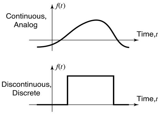
voltage of 4.1V a distance of 100 cm (low light). Notice that this is not a linear relationship,
but voltage is a continuous function of distance. This type of continuous sensor is known as an
analog
sensor. Sensors that only provide
discrete / discontinuous values such as on/off mechanical switches are known as
digital
sensors. The following figure
illustrates the difference between the two types of sensors.
In Lab #1
digital input pins were introduced as a way to measure on/off digital
voltages. Digital inputs cannot
accurately measure analog voltages because there are only two states which are
measured: LOW (0V) and HIGH (5V).
Therefore, a different type of input is required. The Arduino board has 8 analog input pins (A0
to A7), often called Analog to Digital Conversion (ADC) pins, that are capable
of measuring continuous / analog voltages.
The default voltage range for these inputs is 0V to 5V, but it can be
adjusted for smaller ranges using a library function. The voltage from the sensor is connected to
one of the analog input pins. The ground
of the sensor is connected to the GND pin of the Arduino (forming a common
ground / reference). The Arduino analog
input function returns integer values from 0 to 1023 (10-bit resolution)
directly proportional to the input voltage (0 to 5V). Note that it takes approximately 100 us to
read an analog input. Thus, relatively
fast analog signals can be measured such as audio and vibrations.
One might ask
why do we use digital inputs when analog inputs are more general ? Digital inputs are faster, more efficient,
and less expensive so they are normally preferred for on/off sensors and
actuators. Digital inputs are also less
sensitive to noise because there are only two voltages 0V and 5V which are
separated well beyond most noise levels.
Note that
some of the DIO pins (6 of them) can be used to approximate analog outputs
using pulse width modulation (PWM). PWM
analog outputs are useful for interfacing with some types of motors such as DC
brushed motors in flying drone thrusters.
This will be the subject of an Arduino lab for some other course.
The Arduino
library uses C++ objects known as “Servo” in order to command the servo
motors. If you have not yet formally
covered objects in class don’t worry.
Programming objects can be challenging, but using them is not so
hard. You have probably already used
cout and fout which are also objects. In
order to use Servo objects you must include <Servo.h> at the top of the
program. An object is basically like a
new type of variable that has some extra features compared to standard variable
types such as int and double. Each servo motor connected to the Arduino
requires its own Servo object / variable.
For example,
#include
<Servo.h> // include file for servo motors
Servo
servo1; // declare global Servo object /
variable for servo motor #1
Servo
servo2; // declare global Servo object /
variable for servo motor #2
void setup()
{
servo1.attach(7); // connect pin 7 to servo motor #1
servo2.attach(8); // connect pin 8 to servo motor #2
}
void loop() {
servo1.write(7);
// command servo motor #1 to go to 7 deg
servo2.write(27);
// command servo motor #2 to go to 27 deg
}
This example
tells the Arduino that servo1 and servo2 control the servo motors connected to
pins 7 and 8, respectively. It then
commands servo motor #1 to go to 7 deg and servo motor #2 to go to 27 deg.
Note the
expectation for this lab is that you can use Servo objects after studying the
examples. You are not expected at this
stage to know objects or how to make them.
Just use the examples like building blocks / Legos for now.
Programming
the Arduino
At this point
you can test your setup and run the programming examples. Connect the USB cable to the Arduino and
PC. Then plug in the power supply.
Lab Tip: If you smell anything like plastic burning
then quickly remove the power supply from the outlet and remove the USB
connection from the PC. Ask the lab
instructor to check your connections in that case.
Expand
“arduino_lab2.rar” given below into a separate folder. Open the “arduino_lab2.ino” file in the
Arduino IDE. After you compile and
upload this program the servo motor should go backward and forward and the light
sensor output should print out the screen.
The light output should change between 0V and 5V depending on its
proximity to light. At this point you
can watch the videos and perform the rest of the lab.
This video
covers the main programming part of the lab
http://users.encs.concordia.ca/~bwgordon/arduino_lab2.mp4
This video
provides some additional example / exercise problems
http://users.encs.concordia.ca/~bwgordon/arduino_lab2_examples.mp4
A rar file
that contains the source code files for this lesson is provided here
http://users.encs.concordia.ca/~bwgordon/arduino_lab2.rar
Lab
assignment
1) The noise
level of a sensor can be obtained by repeatedly measuring a sensor for a
constant input (e.g. fixed level of light) and calculating statistics for a
large number of measurements (e.g. N = 1000).
The average value is the best estimate of the sensor measurement
(assuming the input is not changing).
The range delta is given by the difference between the maximum and
minimum sensor values measured (i.e. delta = max - min). An estimate of the noise level is given by
delta / 2. It should be noted that all
sensors have some noise and this noise causes uncertainty in measurements. Averaging can be used to reduce the effect of
noise if the sensor has a constant or slowly changing input. It can be shown that the noise level of an
average measurement is approximated by delta_ave = 0.5 * delta / sqrt(N). Therefore, averaging 25 measurements reduces
the effective noise level by a factor of 5.
Determine the
average value of the light sensor (for a constant light input) and estimate the
noise level of the sensor (N = 1000) for measurements made at approximately 1ms
intervals. Repeat the test for different
levels and types of light (LED, phosphorescent, old fashion light bulbs,
etc.). Note any differences in the noise
levels and try to explain the variations.
2) Connect
the second servo motor to Arduino pin 8.
Then connect the black line of the servo motor to an input of the GND
lever nut and the red line of the servo motor to an input of the 5V lever nut
(see the picture in the wiring section) using appropriate jumper wires. Place
small pieces tape on both servo discs so you can clearly see their motion.
Write a
program that moves the servo motors (servo #1 = pin 7, servo #2 = pin 8) as
follows for 60s
th1_d = A*(
1.0 + sin(w*t + phi1) );
th2_d = A*(
1.0 + sin(w*t + phi2) );
where A = 45
deg, w = 1 rad/s, phi1 = 0, phi2 = 0, and t is the time in seconds read from
the Arduino clock. In this case the
servo motors should move in phase (i.e. in the same direction). Try changing phi2 to 3.14159 (180 deg) and
observe that the servos move completely out of phase (i.e. opposite
directions).
3) Attach the
light sensor to a servo disk (using tape, weak glue, etc.). Write a program that maximizes the light to
the sensor by adjusting the angle of the servo.
Test the program by placing a stationary light (LED, cell phone, etc.)
near the sensor. Plot light level vs
time in Excel (or another spreadsheet program such as LibreOffice).
Note there
are two basics approaches you can use to maximize the light. The first approach slowly moves the servo
over its complete range and measures the light for each angle. It then moves to the angle with the highest
light measurement. The second approach
measures the light for three consecutive angles in a small range (theta - d,
theta, and theta + d) a small distance apart (e.g. d = 3 deg), where theta is
the current angle of the servo. The
servo then moves to the angle with the highest light level. This process is then continually repeated in
order to slowly maximize the light level.
Different values of d will result in different convergence times. You can use either approach (or try both) to
solve this question. Make sure to give
the servo motor enough time to reach its destination. This reaching time will be directly
proportional to the distance that must be traveled since the last command. However, any sufficiently large value such as
100 ms will work.
4) Think
about how you might incorporate the material from this lab into your robot.