

Next: The Box Layout Up: No Title Previous: Layout Specifications


Next: The Box Layout
Up: No Title
Previous: Layout
Specifications
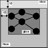
The previous section introduced our three basic box types and their associated layout algorithms. Apparently, it is not reasonable to describe every layout with the box-and-glue metaphor. An obvious example is a set of nodes arranged as a graph. We provide a means for integrating these special layout descriptions with the box-and-glue mechanism. Our layout language has the notion of a user-defined box : (<layout-name> <arg-1> ... <arg-n>). For instance, with <layout-name> being :dag we have (:dag <roots> <successors> <depth> <appearance>), i.e. the layout of directed acyclic graphs (DAGs) is specified (see Figure 4). In this (simplified) example the items to be arranged are defined inductively by a set of roots, a function responsible for generating successors of a node, a maximal graph depth, and a function which is used to compute the graphical representation of nodes.
Position and size of the associated box are defined implicitly by a closure rectangle around all graph items (see Figure 4). This rectangle defines a box which may be arranged using the box layout specifications already known.
One may also think of other arrangements of box items in a user-defined box. For instance, a new layout interpreter can be provided by the following form.1
(deflayout :dag (layout-specs)
  "Returns (generated and) laid out DAG elements."
  (interpret-dag-layout layout-specs))
The layout name (e.g. :dag) of a user-defined box form is used as a key to discriminate the corresponding layout interpreter, the rest of the form is passed to the parameter -specs. In order to determine size and position of objects found in -specs certain generic functions (e.g. (setf box-item-size), (setf box-item-position)) have to be used. Appropriate methods may be supplied for items to be positioned using the layout descriptions.
(let ((upper-offset 10)
      (left-offset 10))
  (:vbox ()
    upper-offset
    (:hbox () left-offset
      (:dag *roots*
            #'successors
            *max-depth*
            #'appearance
                  ...))))
|  |
Figure 4: A general layout specification in combination
with a box-style layout.2
Using the layout descriptions described in the previous sections, it is easy to determine the position of graphical objects relative to a global window, say. In other domains (such as graph layout) objects are dependent on one another (e.g. concerning size and position). In our graph example edges are dependent on graph nodes, i.e. position (and size) of the edges can be computed by referring to the nodes. Since nodes can be moved, the referenced position may change. We generalized these ideas in the following way.
References can be established between any two graphical objects. In technical terms: the reference facility can be supplied to graphical objects by defining -mixin as one of their superclasses. Corresponding coordinates (stored in reference objects) are automatically (re)computed and appropriate redisplay methods are evaluated to update the display accordingly when a referenced object is moved (or dragged). The drawing function of an edge retrieves the computed references and draws the connecting line accordingly.
References are specified by a reference box (:rbox ...). A reference box consists of two view items, the referencing item (e.g. A) and the referenced item (e.g. B), and a pair of horizontal and vertical coordinates specifying the location which is referenced.
(:rbox A B
       (:horizontal :filler :reference :filler)
       (:vertical :filler :reference :filler))

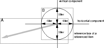
Figure 5: Location referenced inside of item B.

Figure 6: Location of edges defined by node references.
This box defines a reference from item A to item B. The keyword :reference is used to specify the horizontal and vertical coordinates of A's reference point inside of B's drawing rectangle. Fillers ensure the centering of this reference point. Figure 5 illustrates this type of reference. The start point of the gray vector defines A's reference to the center of B (circle). The orientation of the vector depends on A's position which is not shown in this example. The reference box of B (its drawing rectangle) is shown as gray rectangle. The next example defines a reference point whose location is 3 pixel above to and left from the lower right corner of item B.
(:rbox A B
       (:horizontal :filler :reference 3)
       (:vertical :filler :reference 3))
We apply the concepts introduced insofar to define a class edge-view representing edges in a graph. The end points of an edge are specified as references to corresponding nodes. In order to compute the coordinates of the two points defining the edge (see Figure 6), the drawing function of edge-view uses the predefined functions references-of-this-view and reference-position .
(defclass edge-view
  (reference-mixin view) ; MCL class view provides a local coordinate system
  ()
  (:documentation "Edge in a graph."))

(defun make-edge (...) ...)

(defmethod view-draw-contents ((view edge-view))
  (let* ((references (references-of-this-view view))
         (p1 (reference-position (first references)))   ; first point
         (p2 (reference-position (second references)))) ; second point
    (move-to view p1)                     ; set pen position
    (line-to view standard-gcontext p2))) ; draw edge between p1 and p2
If the location of the rounded rectangles (Class-1, Class-2) is changed, the reference points P1 and P2 are recomputed and the line is redrawn.
The layout specification of our class browser uses reference boxes to define node-connecting edges. The following specifications replace and supplement the specification given in Section 2.3.
(setf (layout graph-view)
      (:vbox ()
        10     ; 10 Pixel upper border
        (:hbox ()
          10   ; 10 Pixel left border
          (:dag (list (find-class class-name))   ; list of DAG roots
                #'class-direct-subclasses        ; successor function
                *hierarchy-depth*                ; max. expansion depth
                #'(lambda (class) t)             ; expansion predicate
                #'(lambda (class)                ; node-creating function
                    (make-node (class-name-as-string class)))
                #'make-edge                      ; edge-creating function
                #'western-reference              ; start point of edge
                #'eastern-reference))))          ; end point of edge

(defun western-reference (referencing-object referenced-object)
  "Definition of reference points with :rbox form. A function is used
   to handle the parameter bindings."
  (:rbox referencing-object referenced-object
         (:vertical :filler :reference :filler)
         (:horizontal :reference :filler)))

(defun eastern-reference (referencing-object referenced-object)
  "Definition of reference points with :rbox form"
  (:rbox referencing-object
         referenced-object
         (:vertical :filler :reference :filler)
         (:horizontal :filler :reference)))
The reference elements introduced insofar are implemented as a set-like data structure. For instance, it is not possible to define directed references since their start and end points could not be identified. Therefore, we extended our reference boxes for supporting a naming mechanism. Names may be assigned to descriptions of reference boxes. These names enable the user to define higher-level abstractions such as directed references. For instance, the following specifications define the start and end point of an object arrow, which points from the lower right corner of object node-1 to the upper left corner of object node-2.
(:rbox :arrow-start arrow node-1
       (:horizontal :filler :reference)
       (:vertical :filler :reference))

(:rbox :arrow-end arrow node-2
       (:horizontal :reference :filler)
       (:vertical :reference :filler))
The predefined function find-reference can be applied to a reference name (e.g. :arrow-start) and a list of references and returns the corresponding reference. For instance, this feature is used by an arrow-drawing method for determining the arrow direction.
(defmethod view-draw-contents ((view edge-view))
  (let* ((references (references-of-this-view item))
         (p1 (reference-position (find-reference ':arrow-start references)))
         (p2 (reference-position (find-reference ':arrow-end references))))
     (draw-arrow view standard-gcontext p1 p2)))
These examples demonstrated the usefulness of our layout extensions, which have been fully integrated with our box layouts. We think of reference boxes as a convenient, simple, and computationally cheap way for specifying local dependencies between graph elements. Since efficiency is a major concern of our approach, the next section explains some of our considerations regarding our box layout algorithm in more detail.


Next: The Box Layout
Up: No Title
Previous: Layout
Specifications