The estimation of core losses is important in designing, uprating, and upgrading of electrical machines. Specifically, the need for highly efficient energy conversion devices with increasing high power density (frequency and magnetic loading), the accurate prediction of core losses is important. This requires state of the art core loss measurements, accurate core loss modeling, and application of the above to design and uprate studies.
a)
Measurements
Electric machine stator core and T-joints of three phase
transformers
are subjected to both pulsating and rotational fluxes. This requires
different
measurement methods and setups.
i. Pulsating
core loss measurements
Conventionally, core losses are measured using the Epstein, single sheet and toroid testers according to ASTM and IEC standards. These standards are specific to the type of the setup, flux density, and frequency measurement range.
PEER research
group has the capacity to measure both low and high
frequency (10 Hz to 4 kHz) core losses, on standard and non-standard
samples.
The test can be done under both sinusoidal and non-sinusoidal pulsating
fields.
 |
 |
 |
 |
| (a) Toroid tester | (b) Single sheet tester | (c) Epstein frame | (d) Stator core toroid |
ii. Rotational
core loss measurements
Pulsating and rotational magnetizations differ in their loss mechanism. As such, they result in different core losses. The aspect-ratio, a ratio of the minimum to the maximum radii of a flux density locus is used to categorize magnetization into pulsating, elliptical and rotating. Aspect-ratios greater than zero (r > 0) are referred to as rotational.
The PEER
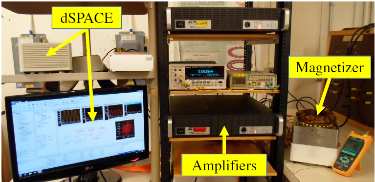
research group has developed the capacity to measure rotational
core losses in the range of 60 Hz to 1 kHz, using the round rotational
single
sheet testers (RRSSTs) shown in
Figure (2).
Moreover, the stator-based RRSST can achieve
higher flux densities in the order of 2 T at 60 Hz.
 |
 |
 |
| (a) Halbach RRSST | (b) Stator-based RRSST | (c) Rotational core loss measurement test bench |
Measurements are important in determining and initializing model parameters, and in the validation of the models.
b) Modelling
The classical
Steinmetz (two-term) and the three-term model coefficients
are usually determined from loss separation and curve fittings. These
coefficients are modified to extend their application to higher flux
densities
and frequencies. Results that are more accurate have been realized and
validated by considering the skin effect, minor loops, and the adoption
of the
energetic model. This has allowed the prediction of core losses under
both
sinusoidal and non-sinusoidal pulsating flux densities. This work is
being
extended to rotational core loss measurements.
c) Applications
Core losses
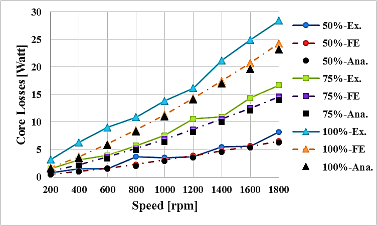
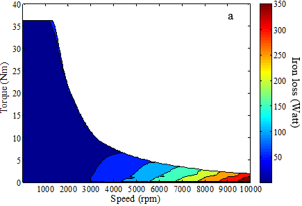
have been analyzed in a variable flux PM machine, and some of
the results are shown in
Figure (3).
The inherent capability to demagnetize the
magnets allows the estimation of core losses in these machines,
analysis of the
build factors, switching schemes, and improvement of efficiency in the
flux-weakening region.
 |
 |
| (a) Rotor of the variable flux PM machine | (b)
Experimental, simulation and analytical core losses at different magnetization levels |
 |
 |
| (c) Core loss distribution in 100 % magnetization | (d) Core loss distribution in 25 % magnetization |
In addition, core losses are
invaluable in the uprating and
upgrading of
large MW rated machines, used in power generation and large mills such
as
cement factories. Increasing the rating of a machine requires the
accurate
prediction of hotspots - the potential failure locations. Hence,
rotational and
non-sinusoidal core loss measurements are imperative in uprating
studies. There
is ongoing research in the accurate prediction of core losses in the
uprating
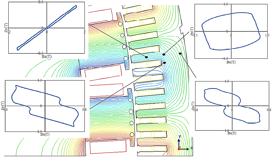
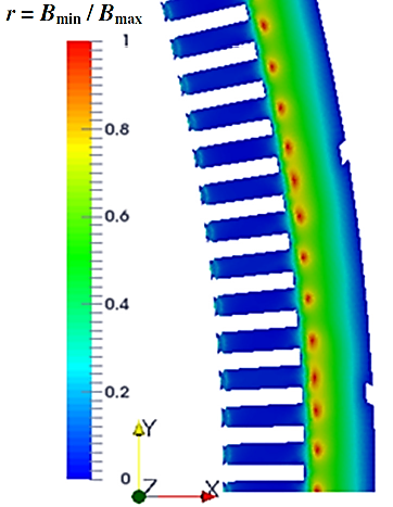
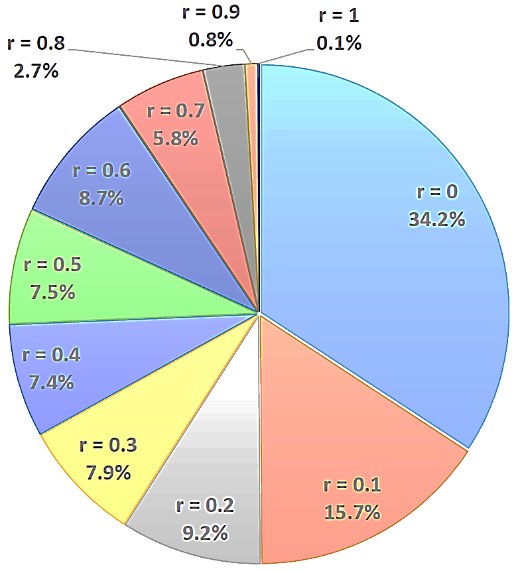
of a 19 MVA hydro generator. Figure (4) shows the presence of
non-sinusoidal pulsating
and rotational fields, and their distribution in the stator core this
hydro
generator. In addition, Figure (4) (c) shows that rotational zones are
greater
than 50 % in this stator core.
 |
 |
| (b) Aspect-ratio map | (c) Aspect-ratio percentage distribution |
In conclusion,
there is more work to be done in extending the
measurements to DC, higher frequencies and flux densities, under both
sinusoidal and non-sinusoidal flux densities. The application of core
losses in
machine design or any related study is challenging. This is because
they are
affected by other factors such as handling, type of cutting, stacking
pressure,
and other build factors that are difficult to model and test. Hence,
the
predicted and the measured core losses differ. There is room for more
research
in the consideration of build factors in terms of measurements,
modelling, and
application.